Design and build a drone from scratch
How to use a Raspberry Pi, Platypush and some cheap electronics to build your own drone.
Drones are increasingly popular and affordable nowadays, and they have become a popular toy for kids and adults of all ages. If all you need is a flying camera to take your holiday selfies then an off-the-shelf solution may be good enough. If instead you want something a bit more customized, or you just enjoy the pleasure of building things from scratch to understand how they work (and few things give more satisfaction than seeing something you have built lift off the ground), then you are in the right place.
This article is about designing and building a drone completely from scratch and is divided in four parts.
The first part covers the physics of lift, both under an aerodynamic (how to pick the right motors and blades and how to use them to generate lift) and an electric perspective (how lift power and time-of-flight relate to battery capacity and discharge rate and how to optimize your design).
The second part covers the hardware side, how to get the frame in place, which electronic components to pick, how to wire them together, how to place them on the body of the drone and how PWM modulation works.
The third part covers the software side, specifically how to code a flight controller on a Raspberry Pi as set of Python scripts that run on top of Platypush.
The fourth part shows how to put all things together, calibrate and fly your new drone.
Disclaimer
A disclaimer is owed before we start.
Drones are devices that use rigid propellers that spin hundreds or thousands of times in a minute. That's at least ten times faster than your regular table fan. Needless to say, if those things touch your fingers you can get very, very hurt. Moreover, these propellers are usually powered by high-power lithium batteries that spit out lots of current to ensure that they can run so fast. If any of the connections between your propellers and the battery are loose, you may get some bad sparks as soon as you try and fly your drone - and nothing nice can happen if those sparks touch the battery.
So some precautions are due before you assemble and start anything:
-
NEVER, ever run your drone with the blades mounted unless you have completed the calibration phase, and you are REALLY sure that you can quickly switch everything off in case your drone leaps towards your face.
-
As a corollary of the point above: ALWAYS make sure that you have a kill switch (either hardware or software) to physically cut the power from the motors before your drone damages objects or living beings.
-
Second corollary: when you are in the initial calibration phase of your drone, or you are checking that all the connections are fine and that the motors spin in the right direction, ALWAYS do it without the blades mounted.
-
ALWAYS make sure that the drone has enough room around before starting the motors, and that no wires nor other mechanical obstacles are on the path of the propellers when they spin.
-
ALWAYS pay attention when you work with large LiPo batteries. They are amazing and can store a lot of juice, but they are also ready to go on fire on the first mistake. Make sure that none of the moving parts is ever touching the battery - even a small puncture can cause the battery to smoke, as the oxygen from the air comes in contact with the electrolytes of the battery. NEVER overcharge them and never over-discharge them - refer to the manual for the advised voltage range. NEVER short-circuit them.
-
ALWAYS make sure that all the connections between the battery and the motors (including those to the power board, to the ESCs and to the motors) are stable and well soldered. When you install electronics on things that can move so fast, even a small loose connection can be a recipe for disaster. Also, make sure that all the wires and electrolyte capacitors are installed with the right polarity.
-
Consider installing physical protections for your propellers.
-
If you are planning to fly the drone outdoor, remember to check your local rules, and always behave responsibly: after all, you are flying DIY vehicles in public areas.

With these recommendations out of the way, let's start getting our hands dirty with a bit of theory about drones and lift.
The physics of a drone
The physics of lift
This section will include some theory on how to get drones (and things in general) to lift and fly. I would advise to do these calculations before you start assembling or even order components for your drone: flying objects rely on delicate physical balances. If you get any of the variables wrong (e.g. you assemble a drone that is too heavy for what the propellers can lift, or you install a battery that can't provide enough current for lift-off) then you'll only notice it when the drone is completely assembled, and it'll take time, money and effort to disassemble the drone, redesign it and reorder components in order to address these issues (I have learned this the hard way). Time to dust off some physics books!
A quadcopter flies by displacing air through the quick rotations of its propellers. The blades of a propeller share a similar structure with wings, and both are designed to move air at a higher speed above them than the air below. A wing is designed to "cut" through the air at high speeds, causing the air above it to move as fast as the wing but in the opposite direction (3rd Newton's law a.k.a. action-and-reaction). This movement ends up creating a pocket of air with lower pressure and higher speed on the top of the blade. This volume of air is forced to flow downwards along the structure, and it meets the bottom flow of air at the tip of the blade. This movement causes the air at the bottom of the blade to apply an upward pressure towards the bottom of the propeller that is higher than the downward pressure applied to the top. The imbalance between the pressure of the two columns of air (above and below the blade) is what causes the attached structure to lift.

The first fundamental definition when it comes to drone flight is that of static thrust  . The static thrust
is informally defined as the force that the propellers need to provide to the vehicle to maintain it in stationary
conditions. When the drone is hovering, this is basically the force that the propellers need to apply to the vehicle
in order to balance its weight and keep it in position. Calculating this force is fundamental to design any vehicle that
can fly, albeit it's not a sufficient condition: to actually get a vehicle to lift off you first need to apply a force
. The static thrust
is informally defined as the force that the propellers need to provide to the vehicle to maintain it in stationary
conditions. When the drone is hovering, this is basically the force that the propellers need to apply to the vehicle
in order to balance its weight and keep it in position. Calculating this force is fundamental to design any vehicle that
can fly, albeit it's not a sufficient condition: to actually get a vehicle to lift off you first need to apply a force
 , so you should usually design a drone in such a way that its propellers can provide a thrust at least 25%
higher than its static thrust.
, so you should usually design a drone in such a way that its propellers can provide a thrust at least 25%
higher than its static thrust.

Intuitively, the thrust provided by a propeller must be somehow proportional to the velocity of the air it displaces. The higher the speed of the air it moves, the lower its pressure, the higher the gradient of pressure between the air above and below, the higher the lift it can provide. A formalization of this intuition is provided by the Bernoulli's principle, which states that air pressure p and velocity v at any point in space are connected by the following relation:

where  is the density of the medium (in this case air).
If we now define  as the pressure of air below the blade,
  the pressure above,
  as the speed
of air before it hits the blade and
as the speed
of air before it hits the blade and  as the speed of air after it is accelerated by the blade,
then we must have:
as the speed of air after it is accelerated by the blade,
then we must have:

The difference in air pressure that generates the lift can therefore be written as:

We can picture how air speed and pressure change when they are accelerated by a propeller with diameter d (and how the width of the column of air changes as well) through this diagram:

We also know that pressure equals force divided by area, therefore the thrust must equal the difference of pressure times the area of the propeller A:

The area of a propeller moving at very high speed can be approximated as the area of a circular disc whose diameter equals the diameter of the propellers:

Therefore we can rewrite the thrust as:

If we replace  with
with  we get:

We can assume that  , i.e. the velocity of air far from the propellers is zero (this may not be a good
approximation when you operate the drone in a windy or highly turbulent environment though). With this assumption, the
formula can be simplified to:
, i.e. the velocity of air far from the propellers is zero (this may not be a good
approximation when you operate the drone in a windy or highly turbulent environment though). With this assumption, the
formula can be simplified to:

This equation provides two very valuable pieces of information when it comes to designing our drone:
-
The thrust is proportional to the square of the diameter of the propellers. If you double the diameter of the propellers then the thrust increases by 4. If you triple it then it increases by 9, and so on. However, larger propellers tend to have larger mass, the motors have to apply a greater force to spin them, and they generate greater air turbulence, resulting in drones that are harder to control.
-
The thrust is proportional to the square of the variation of speed of the air around the propellers. Propellers that can displace more air can generate more thrust. The more obvious way to increase the speed of air is to increase the speed of the propellers by applying a higher current to the motors. Another way is to increase the number of blades on the propellers (more blades will cause more air to move, which in turn causes a greater difference in velocity), but a higher number of blades tends to also increase air turbulence. Usually a two blade configuration is used for most of the commercial drones, while a three blade configuration is often used on racing drones or high-power vehicles. Also keep in mind that the efficiency of a real propeller goes down when
 becomes
too high (that's because a higher gradient of velocity means a higher turbulence when the air flowing on top of the
wing meets the air below at the edge of the blade), so you may want to strike a balance between thrust generated
by air displacement and propeller efficiency.
becomes
too high (that's because a higher gradient of velocity means a higher turbulence when the air flowing on top of the
wing meets the air below at the edge of the blade), so you may want to strike a balance between thrust generated
by air displacement and propeller efficiency.
Albeit useful, this equation isn't really the most used when it comes to quadcopter design. That's because it's tricky to build a model that takes into account the velocity of air displaced by each single propeller. Instead, most of the drones rely on electric batteries, and we have better information about battery power, drawn current and voltage than we have about volumes of displaced air or gradients of pressure. So it's convenient to transform velocity into power P, remembering that:

A common convention is to set v as the median between the velocity of air before () and after
() hitting the blade:

We can then rewrite the equation of power with respect to propeller thrust as:

In a real-case scenario, however, not all the energy drawn from the battery is converted into kinetic energy that spins
the propellers. Motors have their own electric efficiency  , which depends on the losses caused by electric
energy transformed to heat during the rotation, and propellers also have their own mechanical efficiency
, which depends on the losses caused by electric
energy transformed to heat during the rotation, and propellers also have their own mechanical efficiency  , mostly caused by the energy dissipated by the drag of the rotors against the air. A good brushless motor has
an electric efficiency around 90%, while a good propeller has a mechanical efficiency between 80-85%. Therefore, the
equation of the actual power that goes into lifting the drone should be rewritten as:
, mostly caused by the energy dissipated by the drag of the rotors against the air. A good brushless motor has
an electric efficiency around 90%, while a good propeller has a mechanical efficiency between 80-85%. Therefore, the
equation of the actual power that goes into lifting the drone should be rewritten as:

Solving for :

Now that we have found a way to express the variation of air velocity in function of the power provided to the propellers, we can rewrite the equation of thrust calculated previously as:

Finally, remembering that  , let's divide both the terms in the equation above by the gravity acceleration
g to get a value for thrust expressed in kg:
, let's divide both the terms in the equation above by the gravity acceleration
g to get a value for thrust expressed in kg:

This is a very useful equation that can be used to design our drone. If we set m equal to the mass of the drone, then we can solve for P and calculate how much power we need to provide to the motors in order to generate a lift that equals the mass of the drone - in other words, this is the power required to achieve static thrust.

We can easily wrap the above formula into a small Python function:
def balance_power(mass, propel_diam, motor_eff, propel_eff):
    """
    Calculate how much power is required to provide a thrust to a
    drone that matches its weight, given a certain configuration
    of propellers and motors.

    :param mass: Mass (in kg)
    :param propel_diam: Propellers diameter (in meters)
    :param motor_eff: Motor efficiency (between 0 and 1)
    :param propel_eff: Propellers efficiency (between 0 and 1)
    :return: The power required to generate a lift that balances the weight
        of the vehicle, in Watts
    """
    import math

    # Air density at sea level and room temperature is about 1.225 kg/m^3
    density = 1.225
    # Gravity acceleration = 9.8 m/s^2
    g = 9.8

    return (
            (1/(propel_diam * motor_eff * propel_eff)) *
            math.sqrt((2 * math.pow(mass,3) * math.pow(g,3))/(math.pi * density))
    )
For example, if you have a drone with the following characteristics:
- mass: 500 grams
- propellers diameter: 5 inches (= 0.127 meters)
- motors efficiency: 90%
- propellers diameter: 80%
We can infer that it takes about 85W of power to generate a lift that balances the weight:
>>> balance_power(mass=0.5, propel_diam=0.127, motor_eff=0.9, propel_eff=0.8)
85.51256229077079
The physics of electric vehicles
The last formula brings us directly to the next topic: once we have figured the dynamics and the aerodynamics, and how much work is required to lift our object, it's time to translate those constraints into electric constraints and size battery, speed controllers and motors accordingly. Importantly, we should also design the system to be able to provide more power than the power required to simply balance its weight - thrust needs to be greater than weight if we want the drone to go up.
You may probably need a powerful LiPo battery if you want to provide your motors with enough power to generate lift for a drone that will sport a Raspberry Pi, a camera, a bunch of sensors, and who knows how much more stuff you are planning to add :) high-power LiPo batteries usually come in packages like this:

High-power LiPo batteries usually come with two types of connectors: XT60 (yellow adapter in the picture above) or T-Plug (original dark red connector connected to the battery in the picture above). Always make sure that the connector of your battery matches the connector of your power distribution board (adapters are available and cheap, but they add a bit of weight and take extra space on the drone).
A LiPo battery usually comes with an indication of its total capacity Q, usually expressed in mAh, and its voltage, expressed in volts (keep in mind, however, that the advertised voltage goes down as the battery discharges, and that also impacts the output power).
You also have an indication of the discharge rate, usually indicated by a number suffixed by C. This number
is used to calculate the maximum current  that the battery can provide without resulting in damage to the
battery itself - this number is the most fundamental cap to the maximum power that a battery can provide. The maximum
current is calculated as the total capacity expressed in amperes divided by one hour and multiplied by the C number.
For example, in the case of the battery pictured above, with an advertised 50C value and 5200 mAh capacity, we have:
that the battery can provide without resulting in damage to the
battery itself - this number is the most fundamental cap to the maximum power that a battery can provide. The maximum
current is calculated as the total capacity expressed in amperes divided by one hour and multiplied by the C number.
For example, in the case of the battery pictured above, with an advertised 50C value and 5200 mAh capacity, we have:

Now that we have the tools to measure the capacity, voltage and maximum current supported by the battery, we can
substitute  in the previous equation of power and, assuming that the voltage is about constant, we can
calculate how much current the motors will absorb to generate a certain lift:
in the previous equation of power and, assuming that the voltage is about constant, we can
calculate how much current the motors will absorb to generate a certain lift:

For example, if the minimum power required to provide stationary thrust is 85W, and the battery works with a tension of 11.1V, then the average current that will be absorbed by the motors while hovering is about 7.6A.
It is very important that this current is lower than - ideally it should be a fraction of ,
or at least half of it to give some headroom during current peaks, especially during lift off, in order to prevent
permanent damage to the battery, so choose a battery with an appropriate discharge rate for the physical characteristics
of your vehicle.
Finally, we can calculate how long the battery will be able to provide a certain current. Knowing that
 , we can express time as a function of battery capacity and required power as:

Where E is the total energy stored in the battery and P is the power we want to provide to the load.
Suppose that a 5000 mAh, 11.V battery is used on our previous 500 grams drone. Then in an ideal case the battery can provide a power of 85W (8A * 11.1V) for:

In reality this value is usually lower (usually at least a half or a third of it, depending on the minimum current
required by the motors to spin) with a non-ideal battery, because below a certain charge left the battery won't be able
to provide the same nominal values of voltage and current, while the formula above assumes that the battery can provide
the same power until the last bit of charge left. However, you can empirically estimate the amount of charge left in the
battery when it starts to struggle to provide the motors with enough torque (you can hear the motors slowing down when
this happens), replace E in the equation above with  , and you can get a more
realistic estimate of the maximum flight time.
, and you can get a more
realistic estimate of the maximum flight time.
Theory in practice
The math that governs the physics of lift and electric power may take a while to sink in, but we can briefly sum up the key takeaways from the formulas above when it comes to designing your drone:
-
The power you need to provide to lift your drone is inversely proportional to the diameter of the blades (larger blades mean more air moved by the propellers, therefore more thrust, therefore less power required). However, larger blades also add up to the total mass, and they also generate greater turbulence, making the vehicle harder to control.
-
The power you need to provide to lift your drone is proportional to the 3/2 power of its mass (a bit more than a linear dependency, a bit less than a squared dependency). So beware of entering the vicious cycle where greater mass requires bigger battery and bigger propellers, which in turn add mass, which in turn requires greater power, and so on.
-
The discharge rate (C) of a battery is an important factor that you should take into account before selecting a battery. Make sure that the battery can provide enough current to achieve static balance given the physical characteristics of your drone.
-
The maximum time of flight for a drone (roughly calculated as the time that a battery can provide enough lift to counteract its weight) in an ideal scenario equals the total energy stored in the battery divided by the power required to achieve static balance.
-
In reality, this quantity assumes that the battery can provide the same power until the last drop of juice left, which is usually not the case for real batteries. For a more accurate number, you should estimate how much charge is left in your battery when the motors start to slow down, and calculate the total time in function of that
 difference.
 -
Larger batteries can provide longer flight time, but they also add up to the total mass, so you may want to find an appropriate trade-off for your case.
Time to get our hands dirty with the real thing now!
The hardware of a drone
Components of a quadcopter
-
Flight controller: This is the "brain" of the drone. It receives commands from an input source and sends signals down the line to control the motors. This is usually the most expensive component of a drone if you want to buy an off-the-shelf circuit. We will be using a Raspberry Pi Zero as a flight controller in this article. That makes the final cost of the drone considerably lower, but it also requires us to write the code for receiving remote commands and for sending the correct signals downstream to the motors.
-
Propellers: These are technically the only moving parts of the vehicle. We have already covered previously how their diameter affects the generated thrust, the required power and the level of air turbulence. Another important consideration is about the number of blades. 2-blades propellers often result in vehicles that are easier to control, even though they may not provide the same acceleration. 3-blades configuration are a bit harder to control, but they usually provide greater acceleration and are preferred for larger drones or racing configurations. The material of the propellers also plays a role, both in terms of robustness and added weight. Carbon fibers propellers are usually preferred in professional applications because of their lower weight and greater robustness, but they come at a higher cost. Plastic propellers are arguably the most common in amateur configurations. Remember: if you are still testing and calibrating your drone, then go for cheap plastic propellers (they will get damaged for sure after a few bumps!), and only use more expensive propellers once you have calibrated the vehicle and mastered the control. Protective shields for propellers are usually also a VERY good idea.
-
Brushless motors: Smaller drones may sometimes opt for brushed motors, but these usually have lower efficiency (75-80% vs. 85-90% for brushless motors) and tend to have a shorter life. However, brushless motors are usually more expensive. The principle of a brushless motor is relatively simple: it consists of two parts, a rotor (the rotating part), and a stator (the stationary part at the center of the motor). Both the stator and the rotor usually include multiple permanent or coiled magnets. An alternate electric current applied to the stator generates a magnetic field, and such magnetic field causes a misalignment between the magnetic fields of the stator and the rotor, continuously attracting or repelling the coils in order to adjust the misalignment, and therefore resulting in a spinning movement.

You can find many brushless motors for quadcopters online. There are a few things to keep an eye on when you select your motors. First, the motor size, expressed as diameter and height of the stator (e.g. 2207 means that the stator is 22mm wide and 7mm tall): bigger motors result in higher torque but they also absorb more power. Then, the kV of the motor, which expresses the ideal number of rotations for each volt applied. The thrust-to-weight ratio expresses how much thrust the motor can generate for each unit of weight - the higher, the better, 2:1 is an acceptable minimum value, 4:1 is considered a middle sweet spot, high ratios such as 8:1 or 13:1 can theoretically be achieved by high-performance motors, but after a certain number of rotations per second spinning a motor any faster is considered inefficient. Finally, you may want to look at the advised number of LiPo cells for the motor. Since high-speed motors drain more power, they usually require batteries with a higher number of cells, as a higher number of cells translates in a higher voltage.
-
Electronic Speed Controllers (ESCs), one for each motor. Brushless motors work thanks to a varying current that generates a rotating magnetic field, but you usually need a component between your controller and the motors to transform the desired motor speed into an alternate current configuration to be applied to the motors. ESCs are small circuits that do exactly this job. A factor to take into account when choosing an ESC is its current specification (in Amperes). That expresses the maximum current that the ESC can deliver to the motors. Make sure that it is higher than the current absorption you have estimated for your drone and lower than the current defined by the discharge rate of your battery.
-
A PWM servo controller: Most of the ESCs out there communicate over pulse width modulation (PWM). This is a quite efficient way to transmit analog signals using the duration (width) of a digital signal. PWM basically allows you to send analog signals using only one digital PIN. We will explore its internals a bit more in depth in the coding section. Unfortunately, even though the Raspberry Pi theoretically has 4 PWM PINs, each of the pairs shares a PWM resource (GPIO 12 and GPIO 18 share a PWM channel while GPIO 13 and GPIO 19 share the other channel). This means that you can actually send a maximum of two distinct PWM signals at the same time, while our quadcopter obviously needs four of them. To solve the problem, you can use a PWM servo controller to extend the PWM capabilities of the Raspberry Pi - a popular choice is the Adafruit 16-channel PWM driver, which, as the name suggests, can control up to 16 independent PWM channels at the same time, and you can even connect up to 62 of these boards to control up to 992 channels, just in case you are planning to design a spaceship.
-
A pair of batteries. I said pair because my advice is to use two separate power sources: a high-power LiPo battery to power the motors, and a small LiPo battery to power the Raspberry Pi and the electronics (a Raspberry Pi Zero that only runs the drone code shouldn't take much power). Even if a high-power LiPo can theoretically provide enough power both for the motors and for the electronics, in reality the motors can suck up a lot of juice when they spin fast, and if the current drops below a certain threshold the Raspberry Pi will just reboot (and you don't want that to happen while your drone is hovering midair). You may also need a LiPo-to-USB power converter like the PowerBoost, whose job is both to provide a USB output from a LiPo source and to stabilize the output voltage and current draw. Keep in mind the previous consideration when you pick the battery to power the motors (weight, charge, discharge rate, number of cells and output voltage).
-
A power distribution board, like this one. First, LiPo batteries for quadcopters have specific connectors (usually XT60 or T-Plug) and you need some kind of adapter to actually connect load to them. Second, these boards are a compact solution to distribute the power of a battery to multiple loads - the board linked above can split the power of a LiPo battery to up to 6 loads.
-
A controller: Most of the commercial quadcopters have radio controllers, but that would add up both to the cost and to the complexity of the circuitry used for the drone. For simplicity, in this article I'll illustrate how to set up any device that exposes a joystick interface on Linux as your controller, with a particular focus on a Bluetooth joystick (Bluetooth can only operate up to 10 meters, but since the Raspberry Pi has a built-in Bluetooth chip it doesn't require USB dongles nor extra RC circuits).
-
A drone frame: You can find many drone frames online for quite affordable prices, or you can easily download a 3D model and print it yourself. Personally I have used this model for my prototype, but this and this are also popular (and more versatile) form factors.
-
A camera to take your amazing pictures and videos from above. We'll use a Raspberry Pi Camera in this tutorial, since it already comes with a RPi native interface, and it doesn't require extra USB dongles and cables.
-
(Optional) a gyroscope: if you want to bring your drone to the next level then you can also add an gyroscope to the Raspberry Pi or a connected microcontroller. The gyroscope measures the gravity acceleration along the three axes. You can easily add some logic to stabilize a drone if the input data from the gyroscope shows that it's leaning too much in one direction.
-
(Optional) a distance sensor: ultrasound, laser or lidar sensors are very useful to study the environment around the drone. You can place one at the bottom of the drone to detect when the drone has touched the ground, or some sensors around the body to detect and avoid possible obstacles.
Putting things together
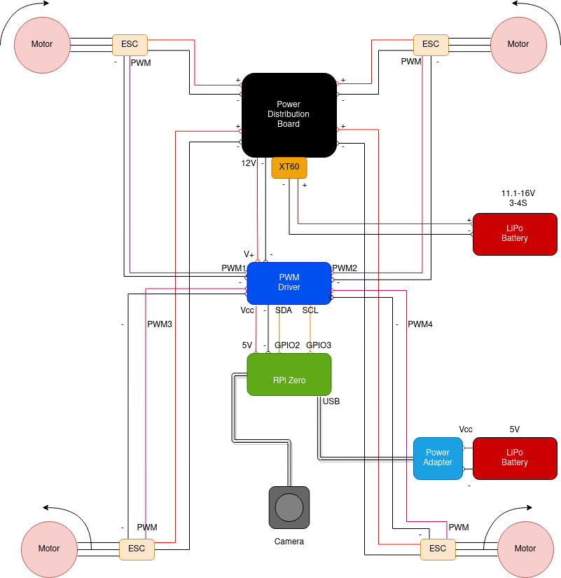
You should now have a clear idea both of how to get a vehicle to lift and which components you need in order to achieve it. Let's put together the ingredients covered in the previous section to show a possible schema for the connections of your components.

A couple of recommendations before jumping in a step-by-step breakdown of the diagram above:
-
Once you have all the components required for your drone, and before starting connecting, soldering and gluing things together, get a scale, put all the components on it and check the total weight. This is the perfect moment to run the calculations shown previously to estimate thrust, power and flight duration of your drone, now that the total mass is known.
-
Play a bit with the placement of your components on the drone frame before you start connecting them together. Given the shape of your frame, study what's the best placement of all the components - Raspberry Pi, PWM driver, camera, power board, batteries, adapters, etc. Make a drawing of their placement, if it helps you remember a particular configuration. Also, study how each component would connect with the others given their placement - the last thing you want is an unmanageable ball of wires going all over the place. Space is limited on the body of a drone, and an optimal initial arrangement of all the components puts your project in a good place.
-
Also, make sure that the weight is more or less balanced. It doesn't have to be 100% balanced on all the four arms, a few grams of difference are still ok, the thrust can be adjusted accordingly during the calibration phase. However, a too heavy imbalance can only be fixed by spinning some propellers at very high speeds, resulting in a higher current drain, shorter duration of the flight, earlier damage to the motors and a harder to control drone.
With these recommendations out of the way, let's dive into assembling our drone.
Frame
Start by mounting the frame. Depending on the frame you bought or printed, this can be a task with a varying level of challenge. When you screw the parts together, remember that plastic screws are lighter than metallic ones. Avoid using hot glue to keep things together: you can use hot glue to stick other components to the frame or hold wires together, but make sure that the frame is sturdy and strong, and that it holds together even without glue. Your drone may fall a lot, and the last thing you want is the drone's body coming completely apart after a small fall.
Once the frame is installed, motors are usually the next logical step. ONLY mount the motors right now, NOT the propellers. Propellers should be installed only when you have managed to calibrate and remotely control the motors, and you are sure that the drone won't flip backwards (or, worst, in your face) once you start giving power to the motors.
Motors and propellers
If you have paid of attention to the previous diagram, you may have noticed that the motors spin in different directions. More precisely, the motors on the opposite diagonals spin in the same direction, and those on the same side spin on opposite directions. The most popular configuration is the following:
- Front-left motor: clockwise spin.
- Front-right motor: anti-clockwise spin.
- Back-left motor: anti-clockwise spin.
- Back-right motor: clockwise spin.
The reason for this configuration can be found in Newton's 3rd-law, a.k.a. "action and reaction".
If a helicopter only had the top propeller and not the smaller propeller on the back, it simply won't fly. Its body will just spin in the opposite direction as the rotation of its propeller. It's the propeller on the back (and the length of the arm that connects it to the body) that balances the spinning movement and provides direction to the vehicle.
Similarly, if all the motors of a drone spun in the same direction then the drone will simply spin in the opposite direction as their rotation. This is because the motors apply a torque to the body of the drone, and the body of the drone responds to this force with a forces that pushes it in the opposite direction. If instead you use an X-shaped configuration, then the rotational components of the four torques cancel each other if they rotate at the same speed, and all you have left is the lift. However, you can still adjust the torques during the flight to temporarily produce a rotation (or yaw) of the drone around its z axis.
Most of the sets of motors for quadcopters already come in pairs that rotate in different directions. The direction of the rotation is usually reported as a small arrow on the side of the motor's body.
Once you have identified the correct spin direction of the motors, install the motors on the body of the drone.
Propellers direction, wind direction and lift
Before proceeding with the other components, we should probably spend two words on the direction of the propellers (again, DON'T install them yet, but just keep these considerations in mind when you are ready to install them).
Propellers for quadcopters usually come in two pairs with wings facing in slightly different directions. If you look at the sections of a set of propellers, you'll notice that they come with two different profiles: they either have the high edge on the left side and the bottom edge on the right side, or the other way around.
We previously mentioned that lift is generated by creating a pocket of fast-moving, low-pressure air on top of the wing opposed to slow-moving, high-pressure air on the bottom. The high-pressure air below the wing ends up applying an upward facing force that causes the vehicle to lift.

If you look at the section of a propeller and picture it against the diagram above, then it's quite simple to figure out which propellers need to be attached to which motors. The propellers should "cut" through the air through the side that faces upwards. Because of Newton's 3rd law, air will start moving in the direction opposite to the spin direction of the motor. This causes the air above the blade to "jump" up, flow downwards along the blade, and eventually apply a higher pressure to the air below it. Therefore, a propeller with the "high" edge on the left of its section needs to be mounted on a clockwise spinning motor, and a propeller with the "high" edge on the right should be mounted on a counter-clockwise spinning motor. If you invert the direction, then no matter how fast you spin the blades, your drone won't move by an inch. That's because, under such configuration, the upper face of each blade would move the air up, therefore the moving air would apply no lift force to the structure of the propeller, and all you have built is a powerful fan to keep you cool in summer.
Setting up the remaining hardware
Once the motors are set up, it's time to glue the ESCs to the frame of the drone and connect the motors to them.
An ESC usually has three wires or soldering pads on one side and five wires on the other. The side with three wires/soldering pads should face the motor and be connected to the three wires coming out of the motor. These wires work as a current tri-phase system with each phase shifted by 120 degrees compared to the others. The shift in the output currents is what generates the alternate current that generates the rotating electromagnetic field that causes the motor to spin. It shouldn't matter in which order you solder these wires to the motor.

On the other side you will usually find a red wire and a black wire, respectively the reference VCC and GND, which need to be connected to the battery through the power distribution board.
Finally, you usually find three additional wires on the same side, usually bundled together in a plastic connector and marked by black, red and white colors. These wires need to be plugged to the PWM circuit board, the red and black cables must be respectively be plugged to the VCC and GND PINs of the board and the white one to the PWM signal PIN.
After you have installed all the four ESCs and connected them to the motors, it's time to install the power supply board and connect the ESCs to it.

Most of the boards for quadcopters have two pairs of power supply connectors for the ESCs respectively on the left and right side. Solder the red wire of each ESC to a + connector and each black wire to the - connector.
After you have mounted the power supply board and soldered the ESC power connectors to it, it's time to move to the PWM servo board that will control the PWM signals sent to the motors.

There may be quite a bit of PINs to solder if you are using the Adafruit 16-channel board. You have to at least solder the following:
-
At least one header of PINs on either the left or right side of the board. These PINs are used to communicate with the Raspberry Pi over I2C interface, so the only connections you really need are VCC (to the Raspberry Pi 3.3V or 5V PIN), GND (to any of the Raspberry Pi ground PINs), SDA (serial data, to the Raspberry Pi I2C SDA PIN, usually GPIO2) and SCL (serial clock, to the Raspberry Pi I2C SCL PIN, usually GPIO3).
-
Four triples of PINs (one per ESC) on the PWM connectors on the bottom side. You will connect the wires from the ESC to these PINs - white wire to PWM, red wire to V+ and black wire to GND.
-
Two PINs or a screwed adapter on the V+/GND connectors on the top of the board. You may want to connect the power supply board 12V/GND connectors here, since most of the ESC devices usually operate around a 9-16V voltage. NEVER connect the V+ line to the Raspberry Pi in any way! 3.3V is supposed to be the maximum voltage of any circuitry connected to the Raspberry Pi. If any higher voltage is present, then the current may start flowing on wrong paths and you may end up damaging your Raspberry Pi for good. So connect the V+ to the power supply board, but make sure that no other V+ PIN is connected to the Raspberry Pi - the only voltage connection to the Raspberry Pi must be through VCC, which should always be in the 3.3-5V range.
-
It's also advised to solder an electrolytic capacitor on the top-left area of the board marked by C2. The electrolytic capacitor provides a voltage buffer to the connected components in case of sudden current spikes or drops.
Once the PWM circuitry is set up, you can move to gluing or screwing the Raspberry Pi Zero. Connect the I2C interface on the side of the Adafruit board to the Raspberry Pi. If we consider the following pinout diagram:

Then you'll need the following connection:
-
PWM board VCC PIN: connect to PIN 1, 2, 4 or 17 (the Adafruit 16-channel PWM board has an operative voltage range of 3-6V).
-
PWM board GND PIN: connect to PIN 6, 9, 14, 20, 25, 30, 34 or 39.
-
PWM board SDA PIN: connect to PIN 3 (GPIO 2/I2C SDA).
-
PWM board SCL PIN: connect to PIN 5 (GPIO 3/I2C SCL).
If you want, you can connect a camera now - simply plug the ribbon cable into the slot on the right side of the board if you are using a Raspberry Pi compatible camera.
Once the Raspberry Pi is mounted and connected to the rest of the circuitry, you can finally proceed with the installation of the batteries. Mount the large LiPo battery on the frame and connect its XT60 or T-Plug cable to the power supply board. If you got all the connections right, you should see both the PWM board and the ESCs power up.
Proceed with the installation of the smaller LiPo battery for the Raspberry Pi. You can use any available LiPo battery shield or adapter available for the Raspberry Pi, there are many options available to power the Raspberry Pi from a LiPo either over a USB adapter or through a shield/hat.
Once everything is connected, it's time to move to the software side of the project.
Prepare the Raspberry Pi
First, you'll need to flash a Linux image to an SD card. Any distro should work, but this article will mostly focus on Raspbian/Raspberry Pi OS because it makes the CircuitPython setup much easier.
Download a Raspberry Pi OS image. I personally used a headless version
(i.e. with no X server nor desktop environment) because you don't really need to plug an HDMI cable, a mouse and a
keyboard that often into a drone and use it like a computer, but if that's one of the use cases that you have in mind
feel free to get a full desktop image. Use any of the supported methods to flash the downloaded image to the SD card,
depending on the host operating system. For instance, the quickest way from Linux would be to simply use dd
(ALWAYS make sure that the /dev file specified actually points to your SD card, or you may risk wiping your own
filesystem):
$ sudo dd if=./raspberry-pi-os-VERSION.img of=/dev/mmcblk0 bs=8M conv=fsync status=progress
Wait a bit (depending on the size of the SD card) and once the copy is done unmount the device and place it into the SD card slot on the Raspberry Pi. Before booting the device, connect it to a monitor over an HDMI cable and connect a wireless/wired keyboard - this may be the only time that you need to actually need to connect the Raspberry to a screen. Boot the device and wait for the partition resize process to complete. You should eventually be prompted to a login screen - use the default credentials, pi - raspberry, to log in.
We may now want to set up Wi-Fi connection, I2C and camera interfaces and SSH access for remote control. This can be
easily done on Raspberry Pi OS through the raspi-config utility:
-
Type
sudo raspi-config. -
Select
System Options->Wireless LANand enter the details of your Wi-Fi network. -
Go back, select
Interface Options->SSHand enable SSH access. -
It's also a good idea to set up auto-login with the
piuser, so a user session with all the required scripts and services will start automatically once the device is booted. This can be done fromSystem Options->Boot / Auto Login->Console/Desktop Autologin. -
The Adafruit PWM servo communicates over I2C interface, therefore make sure it's enabled on the Raspberry Pi (
Interface Options->I2C). -
If you are using a Raspberry Pi camera, you can enable it from here (
Interface Options->Camera). -
Select
Finishand reboot. -
On reboot type
ifconfigorip addrto verify that you are connected to the Wi-Fi network and note down the assigned IP address (you may also want to add a static MAC rule on your router to make sure that it stays the same across reconnections).
Once your device is online, you can unplug the HDMI connection and any mouse or keyboard and restart the Raspberry Pi.
After a few seconds you should be able to ping its IP address, and you can SSH into it from your desktop/laptop through
ssh pi@rpi-ip.
Once you have your remote shell to the drone, update it and make sure that the basic Python dependencies are available:
$ sudo apt update
$ sudo apt upgrade
$ sudo apt install python3 python3-pip
You should now proceed with installing the CircuitPython environment. The PCA9685 chip used by the Adafruit 16-channel PWM board is only compatible with CircuitPython (a minimal installation of the Python interpreter dedicated to IoT and low-power devices), which isn't installed on the Raspberry Pi by default.
Official instructions are
provided on the Adafruit website.
The quickest way if you are running Raspbian/Raspberry Pi OS is probably to install the Adafruit Python shell, download
and run the blinka script:
$ sudo pip3 install --upgrade adafruit-python-shell
$ wget https://raw.githubusercontent.com/adafruit/Raspberry-Pi-Installer-Scripts/master/raspi-blinka.py
$ sudo python3 raspi-blinka.py
Wait a bit for the script to install all the required dependencies, then reboot the device. If everything was
successful, upon reboot you should see a new direct-access block device under /dev/i2c-1. You can now install the
CircuitPython driver for the PCA9685 chipset:
$ sudo pip3 install --upgrade adafruit-circuitpython-pca9685
Set up the controller
Time to move to the controller for our drone. As mentioned earlier, my choice for prototyping is a Bluetooth controller, since the Raspberry Pi Zero already comes with a built-in Bluetooth adapter and connecting it doesn't require any extra wires nor dongles. However, Bluetooth poses a limit on the maximum distance between the drone and the controller, since Bluetooth signals quickly degrade after about 10 meters, and on even shorter distances if there are some obstacles between the sender and the receiver. My advice is therefore to pick Bluetooth in the initial design and prototyping phases, or if you plan to fly the drone mostly indoor or on short distances. If instead you plan to fly your drone more than 10 meters away from you, then you may want to opt for a proper radio controller like this. However, a proper radio set up is usually expensive, and you'll also have to install and configure a radio receiver on the Raspberry Pi as well. Moreover, if you are planning to fly your drone outdoor while viewing its camera feed then you may also want to install a 3G/4G SIM module on the drone, as well as a GPS sensor in order to locate it. These are eventually the most expensive parts that impact the final price of high-range drones, and they are going to be expensive even if you go for the DIY way. So my advice is to make a first prototype using the Bluetooth controller on short range, and once you are confident about your creature then you can make the investment and buy 3G/4G, GPS and RC hardware for a proper remote control and interface.
Sticking to the Bluetooth controller case, first turn it on and put it in pairing mode (instructions differ from device to device, consult the manual of the controller). Once the controller is in pairing mode, start the Bluetooth administration service on the Raspberry Pi and connect the controller:
$ sudo bluetoothctl
[bluetooth]# scan on
...
[NEW] Device 00:11:22:33:44:55 My Joystick
...
[bluetooth]# scan off
[bluetooth]# pair 00:11:22:33:44:55
[bluetooth]# connect 00:11:22:33:44:55
[bluetooth]# trust 00:11:22:33:44:55
[bluetooth]# exit
If the connection was successful you should see a new joystick device under /dev/input/js0. You can test that all
the buttons are correctly detected through the jstest utility:
$ jstest /dev/input/js0
If you can't access the device through the pi user then check its permissions and groups through
ls -l /dev/input/js0. If it has no read privileges for non-group users then simply add the pi user to the
associated group (usually input on Raspberry Pi OS) and reboot the device.
Connect the pieces together
Now that all the hardware is in place and connected, we need to program the "brain" of the drone - the software component that emulates the flight controller, reads commands from the joystick and forwards them to the motors as PWM signals.
We'll use Platypush to connect the pieces together, since it comes both with a plugin for the PCA9685 chipset and a backend to read events from joysticks and joypads on Linux, as well as several plugins and backends to stream camera feeds.
Install Platypush on the Raspberry Pi Zero together with the web server, PCA9685 and PiCamera dependencies:
$ sudo pip3 install --upgrade 'platypush[http,picamera,pca9685]'
Then create a simple configuration file under ~/.config/platypush/config.yaml:
backend.http:
  # Listen port
  port: 8008

backend.joystick.linux:
  device: /dev/input/js0

camera.pi:
  horizontal_flip: False
  vertical_flip: False
  resolution:
    - 800
    - 600

pwm.pca9685:
  # PWM main frequency, in Hz
  frequency: 500

  # Default PWM channels to control.
  # In this case, we have connected the ESCs
  # to the first four channels on the board.
  channels:
    - 0
    - 1
    - 2
    - 3

# when the application starts
event.hook.OnApplicationStarted:
  if:
    type: platypush.message.event.application.ApplicationStartedEvent
  then:
    - action: camera.pi.start_streaming
      args:
        listen_port: 5000
All the sections of the file should be relatively self-explanatory, but the PCA9685 configuration requires a deeper dive in how PWM modulation works under the hood to be properly grasped - we'll dive into it very soon.
In the meantime, you should already be able to start the application through the platypush command
(use the pi user). If everything was installed and configured properly, after a while you should see the camera
sensor turn on - you can view the camera feed either through the
RPi Camera Viewer app for
Android, or through VLC:
$ vlc tcp/h264://rpi-ip:5000
If you turn on and pair your Bluetooth controller you should also be able to see some events in the application log when you press some controls on the device:
...
INFO|platypush|Received event: {"type": "event", "args": {"type": "platypush.message.event.joystick.JoystickConnectedEvent", "device": "/dev/input/js0", "name": "PG-SW021", "axes": ["x", "y", "z", "rz", "gas", "brake", "hat0x", "hat0y", "x", "y", "z", "rz", "gas", "brake", "hat0x", "hat0y", "x", "y", "z", "rz", "gas", "brake", "hat0x", "hat0y", "x", "y", "z", "rz", "gas", "brake", "hat0x", "hat0y", "x", "y", "z", "rz", "gas", "brake", "hat0x", "hat0y"], "buttons": ["a", "b", "c", "x", "y", "z", "tl", "tr", "tl2", "tr2", "select", "start", "mode", "thumbl", "thumbr", "a", "b", "c", "x", "y", "z", "tl", "tr", "tl2", "tr2", "select", "start", "mode", "thumbl", "thumbr", "a", "b", "c", "x", "y", "z", "tl", "tr", "tl2", "tr2", "select", "start", "mode", "thumbl", "thumbr", "a", "b", "c", "x", "y", "z", "tl", "tr", "tl2", "tr2", "select", "start", "mode", "thumbl", "thumbr", "a", "b", "c", "x", "y", "z", "tl", "tr", "tl2", "tr2", "select", "start", "mode", "thumbl", "thumbr"]}}
...
INFO|platypush|Received event: {"type": "event", "args": {"type": "platypush.message.event.joystick.JoystickAxisEvent", "device": "/dev/input/js0", "axis": "hat0x", "value": -1.0}}
INFO|platypush|Received event: {"type": "event", "args": {"type": "platypush.message.event.joystick.JoystickAxisEvent", "device": "/dev/input/js0", "axis": "hat0x", "value": 0.0}}
...
If you see these events it means that the joystick was successfully detected. We'll come back to these events in a bit
to see how to connect them to drone actions. It is now a good idea to configure Platypush as a startup service for the
pi user, so whenever a new user session starts the application will also be started. Get its absolute path:
$ which platypush
Then create a new systemd service file as ~/.config/systemd/user/platypush.service with the following content:
[Unit]
Description=Platypush service
After=network.target bluetooth.target

[Service]
ExecStart=/path/to/platypush
Restart=always
RestartSec=5

[Install]
WantedBy=default.target
Then reload the systemd daemon, start and enable the service:
$ systemctl --user daemon-reload
$ systemctl --user start platypush.service
$ systemctl --user enable platypush.service
It's now time to dive into the PWM internals to understand how to program the controls for the motors through the Raspberry Pi.
Pulse-Width Modulation (PWM) explained
PWM is one of the most common ways of driving electric motors because it makes it easy to transmit analog values using only one digital signal that can either be high or low, and it optimizes power consumption by applying a voltage to the load only when a change to the output power is required. The duration of the high part of the signal expresses the value that you want to transmit, therefore the longer the duration of the high part of a signal, the higher the voltage or current that will be transmitted to the load. Conceptually, PWM is somehow similar to popular radio modulation technologies such as AM or FM, but instead of modulating information through the amplitude or the frequency of the signal, it modulates it through the duration of a digital high signal.
For example, the figure below shows how to transmit a sinusoidal signal B through a PWM train of pulses V. The duration of each pulse expresses how much the output signal should go up (if the voltage is positive) or down (if the voltage is negative) compared to the previous output value. The duration of a high pulse is also called duty cycle.

The most important metric to take into account when designing PWM systems is the base frequency of the modulation process - in other words, how often the signal should be sampled. When driving motors that usually have a minimum and maximum power, you may also want to specify the minimum and maximum duty cycle, i.e. the minimum and maximum duration of a high pulse that will be respectively be mapped to the minimum and maximum output power. It is very important to pick these values in such a way that the minimum value is greater than the sampling period (which is simply the inverse of the sampling frequency). To be more specific, according to Nyquist-Shannon's sampling theorem, the minimum frequency used to deliver actual information must be at least twice the sampling frequency. If that's not the case then some pulses will not be detected, because the duration of the pulse may be shorter than the sampling period.
Most of the ESC controllers on the market have their own supported PWM configurations, and some advanced controllers may even allow more complex controls over PWM - for example for controlling sounds, lights or supporting multiple motor control paradigms. Therefore, the user manual of your ESC (or the chipset used by your ESC) is usually the best place to start before writing the code that actually controls the motors.
In my case I have used some ESC devices with a
BLHeli_32 ARM chipset, a quite popular option for
mid-to-high tier quadcopters - and also a very versatile one, since it's basically a small programmable 32-bit ARM
microcontroller. The
user manual
mentions support for a regular pulse width input between 1-2ms. We can pick 2ms as our sampling period, and
 will therefore be our sampling frequency - configured in the Platypush
 pwm.pca9685 plugin through
the frequency attribute. The manual also mentions support for other PWM configurations (such as OneShot125, OneShot42,
Multshot and Dshot) that usually rely on shorter pulses, but for sake of simplicity (and compatibility with other ESC
devices) we can stick to the regular 2ms sampling period.
Also, the driver of the PCA9685 controller automatically takes care of picking the right duty cycle range given
the frequency, and it maps the duty cycle to 16-bit integers between 0 and 65535. A duty cycle of zero means 0% of the
maximum power, a duty cycle of 0xffff means 100% of the power, a duty cycle of 0x7fff means 50% of the power. The
Platypush wrapper for the PCA9685 uses min_duty_cycle=0 and max_duty_cycle=0xffff unless configured otherwise, but
this is probably not what you want for your drone. You usually want a higher minimum duty cycle because under a certain
threshold the power will be insufficient to even get the motors to spin. And, in most of the cases, you don't want to
have a maximum duty cycle that is 100% of the maximum power. If you have 35A ESC, that will draw 35A from the battery
and, most importantly, it will probably turn your drone into an uncontrollable killer machine. In a general use case you
may want to identify the minimum duty cycle associated to a minimal spin of the motors and pick that as the minimum duty
cycle, and identify the duty cycle associated to a lift-off at the desired speed and pick that as the maximum duty
cycle. We'll see how to use Platypush to calibrate this range through the joystick in a bit.
Finally, most of the ESC devices have an arming sequence. Its main purpose is to prevent unexpected currents or accidental controls from suddenly spinning the motors when it's not desired/required. Therefore, before flying the drone you need to actually send a special PWM sequence that arms the ESC controllers, and sometimes you may need to send another sequence to disarm them (this is usually achieved by bringing the power back to zero, and most of the ESC would automatically disarm after a while if no further pulses are sent).
You should consult the user manual of your ESC to check the supported arming and disarming sequences. For examples, the BLHeli_32 user manual describes the following procedure:

What this diagram says is that:
-
The ESC should beep three times when it's powered on.
-
Once the ESC is powered on, the arming sequence can be initiated by gradually increasing the voltage on the PWM input from 0 to approximately 50% the maximum duty cycle, and then bringing the voltage down back to zero.
-
When the input voltage hits the first low voltage threshold, the ESC emits a first low beep. When it goes back to zero, the ESC emits a high beep.
-
If you hear both the beeps it means that the arming sequence was correct, and you can start stepping up the voltage to actually send power to the motors.
-
If you only hear the low beep, it means that the arming sequence hasn't been successful. It usually means that the pulse train was either too long or too short - its duration should be a multiple of the sampling period, but if it's too much higher then the arming sequence will time out.
-
The deactivation sequence simply consists in bringing the duty cycle to zero and de-initializing the PCA9685 driver.
Now that we have learned the theory of what PWM is, how to use it for signal transmission protocols and how to arm and deactivate an ESC, it's time to get our hands dirty with some code.
Coding the flight controller
Also, be aware: this is the part where you actually spin and test the motors. Once again, do it without the propellers, and double check again that all the connections to the motors are properly set up and that the ESCs are powered on before you try and send any signal.
Create a new script under ~/.config/platypush/scripts/drone.py. This script will contain the automation to control
your drone through the joypad. We first need to code a function to arm the four ESC devices. If you are using a
BLHeli_32-based ESC (or any other ESC device with a double-ramp arming sequence) then you may want to code a function
that uses the pwm.pca9685 plugin to write a zero to the PWM channel, wait a bit, write a value about half of the
maximum duty cycle, wait a bit, and write another zero. And we also need a function that resets the motors by bringing
the voltage to zero and resetting the PCA9685 driver:
import logging
import time

from platypush.context import get_plugin

logger = logging.getLogger(__name__)

def arm_motors():
    logger.info('Arming drone ESCs')
    pwm = get_plugin('pwm.pca9685')
    pwm.write(0)
    time.sleep(0.5)
    pwm.write(0x7fff)
    time.sleep(0.5)
    pwm.write(0)
    time.sleep(0.5)
    logger.info('Drone ESCs ready')

def reset_motors():
    logger.info('Resetting drone ESCs')
    pwm = get_plugin('pwm.pca9685')
    pwm.write(0)
    pwm.reset()
    pwm.deinit()
    logger.info('Drone ESCs reset')
The right time between the writes largely depends on the arming sequence supported by the ESC and it may be a bit of a
trial-and-error process. Many ESCs will emit a particular sequence of beeps or flash their LED in a particular way upon
successful arming sequence. Before you add more code or hook these events to joystick events, open a Python CLI from
the ~/.config/platypush directory and give your logic a test:
>>> from scripts.drone import arm_motors, reset_motors
>>> arm_motors()
# Arming drone ESCs
# Drone ESCs ready
>>> reset_motors()
# Resetting drone ESCs
# Drone ESCs reset
In this case we are not specifying the list of PWM channels to write: if a single value is specified on the .write()
method then the same value will be written to all the channels configured on the plugin, and we previously configured
the pwm.pca9685 plugin to use the first four channels by default.
Once you have managed to arm and disable the ESCs, let's associate these functions to joypad events. For instance, we
can prepare the motors when the joypad connects to the drone and disable them when the joypad disconnects. This can
be easily done in the drone.py script by leveraging the Platypush
JoystickConnectedEvent
and JoystickDisconnectedEvent:
from platypush.event.hook import hook
from platypush.message.event.joystick import JoystickConnectedEvent, JoystickDisconnectedEvent

@hook(JoystickConnectedEvent)
def on_joystick_connected(**_):
    arm_motors()

@hook(JoystickDisconnectedEvent)
def on_joystick_disconnected(**_):
    reset_motors()
Now restart the service on the drone:
$ systemctl --user restart platypush
Then start/pair/connect the joypad. Upon connection, you should see a JoystickConnectedEvent on the logs and the ESCs
should automatically get armed. Now it's a good idea to set up a joystick button to trigger the .reset_motors()
and .arm_motors() methods. This will allow us to programmatically arm/disable the motors without having to
connect/disconnect the joypad. Press the joystick keys that you want to associate to the arm and reset actions while the
application is running and check the associated key code in the logs. For example, if you pick the Select and Start
buttons on a PlayStation or XBox-like joypad:
Received event: {"type": "event", "args": {"type": "platypush.message.event.joystick.JoystickButtonPressedEvent",
"device": "/dev/input/js0", "button": "select"}}
Received event: {"type": "event", "args": {"type": "platypush.message.event.joystick.JoystickButtonPressedEvent",
"device": "/dev/input/js0", "button": "start"}}
So create an event hook in your drone.py script that associates the .arm_motors() and .reset_motors() methods to
these buttons:
from platypush.event.hook import hook
from platypush.message.event.joystick import JoystickButtonPressedEvent

@hook(JoystickButtonPressedEvent, button='start')
def on_start_button_pressed(**_):
  arm_motors()

@hook(JoystickButtonPressedEvent, button='select')
def on_select_button_pressed(**_):
  reset_motors()
Now pick two joystick buttons that you want to use to bring the motor power respectively up and down and log the current duty cycle, and add event hooks for them. For example, during calibration I usually use the L2/R2 buttons on the back of the joystick to respectively bring the power down or up:
import logging

from platypush.context import get_plugin
from platypush.event.hook import hook
from platypush.message.event.joystick import JoystickButtonPressedEvent

logger = logging.getLogger(__name__)
# This defines how much we should take the motor power up or down on each step.
# Feel free to experiment different values for different levels of control.
step = 25

def power_down():
    pwm = get_plugin('pwm.pca9685')
    channels = {
        i: value-step
        for i, value in pwm.get_channels().output.items()
    }

    logger.info(f'Power down. Channel values: {channels}')
    pwm.write(channels=channels)

def power_up():
    pwm = get_plugin('pwm.pca9685')
    channels = {
        i: value+step
        for i, value in pwm.get_channels().output.items()
    }

    logger.info('Power up. Channel values: {channels}')
    pwm.write(channels=channels)

@hook(JoystickButtonPressedEvent, button='tl2')
def on_power_down_button_pressed(**_):
    power_down()

@hook(JoystickButtonPressedEvent, button='tr2')
def on_power_up_button_pressed(**_):
    power_up()
Now restart the service and arm the ESCs. Once armed, press R2 repeatedly to bring up the power provided to the motors.
At the beginning the motors might not move at all, but once passed a certain current threshold they will start spinning
lightly. Take note of the power configuration required to achieve a minimum level of spin on the motors, it should now
be reported on the application logs. This is going to be the min_duty_cycle on the pwm.pca9685 plugin configuration,
since any lower currents won't cause any change to the speed of the motors. Some motors may also have an upper boundary
for the maximum current that could be lower than the maximum current that can be delivered by the ESCs. If that's the
case, then the motors will usually automatically stop. If you notice such behaviour while powering up the motors, then
configure the associated duty cycle as max_duty_cycle. For example, this configuration seems to work quite well for my
combination of motors and ESCs:
pwm.pca9685:
    frequency: 500
    min_duty_cycle: 2000
    max_duty_cycle: 4000
    channels:
        - 0
        - 1
        - 2
        - 3
Now that we have some commands configured to arm and reset the motors, and some logic to increase or decrease the power, we can proceed to calibrating the drone.
Drone calibration
This is the moment of truth of the project: you can now set up the propellers on the motors and verify that your creature can move (follow the previous instructions about the direction and the order of the blades).
However, before calling your friends to show off your new drone, you may consider calibrating the motors - and this may be a quite time-intensive process.
In theory, sending the same current to two motors should cause the same torque on the body of the drone. However, many
factors (such as small production differences between individual motors, distribution of the weight on the frame or
different level of friction between the stator and the rotor) usually cause the motors of a drone to behave slightly
differently. If the torques of the motors are not perfectly balanced, then the drone will either spin around its body or
flip in the direction opposite to the one with the strongest torque. Therefore, you may want to add to your drone.py
script a mapping of the current offsets for each motor. A smaller value means that less current will be provided to
that motor compared to the others, a greater value is the other way around. For now let's initialize this table with
zeros:
class Channel:
  """
  Motor position to PWM channel index.
  """
  TOP_LEFT = 0
  TOP_RIGHT = 1
  BOTTOM_LEFT = 2
  BOTTOM_RIGHT = 3

offsets = {
    Channel.TOP_LEFT: 0,
    Channel.TOP_RIGHT: 0,
    Channel.BOTTOM_LEFT: 0,
    Channel.BOTTOM_RIGHT: 0,
}
Now let's wrap the .arm_motors() method into a .warmup() method that does the following:
-
Arms the ESCs.
-
Increases the current sent to the motors by gradually increasing the duty cycle to each of the ESCs until
min_duty_cycle + offset[i]. This will get the motors to rotate at low speed. -
The joystick
startbutton will call this.warmup()method instead of.arm_motors().
The logic will look like this:
import logging

from platypush.context import get_plugin
from platypush.event.hook import hook
from platypush.message.event.joystick import JoystickButtonPressedEvent

logger = logging.getLogger(__name__)

def warmup():
    arm_motors()
    logger.info('Starting the propellers!')
    pwm = get_plugin('pwm.pca9685')

    # Start from 50% of min_duty_cycle
    channels = {
        channel: int(0.5 * pwm.min_duty_cycle) + offset
        for channel, offset in offsets.items()
    }

    pwm.write(channels=channels)

    # Bring the power up to min_duty_cycle
    channels = {
        channel: pwm.min_duty_cycle + offset
        for channel, offset in offsets.items()
    }

    pwm.write(channels=channels, step=15, step_duration=0.03)

@hook(JoystickButtonPressedEvent, button='start')
def on_start_button_pressed(**_):
  warmup()
Now it's time to remind a few precautions:
-
Make sure that there's enough room around the drone and that it's sitting on a large surface.
-
Make sure that no obstacles or people are present in a radius of at least 2-3 meters from the drone.
-
Remember that once the motors have the propellers attached and you start loading a lot of current into them, whatever you attached to them will start moving. But you haven't calibrated the motors yet, so you don't know yet in which direction the drone will move. Behave accordingly.
With your drone sitting in a safe spot, it's time to restart Platypush, trigger the .warmup() function and start
powering juice to the motors. At some point you'll hopefully start seeing the drone hover and slightly move in some
direction. This is the moment where you should pay most of the attention, for two reasons:
-
You know have an uncalibrated hovering device with blades that spin hundreds of times a second, and you know the rules: as soon as anything goes wrong, hit that
.reset_motors()button! -
It's very likely that the drone won't simply move up straight from the floor at this stage, because some motors may generate a lower or higher torque than others.
-
Unless you have been very lucky on the point above, the first time you try and fly the drone it'll move in some random direction. Therefore don't provide too much power to the motors - you don't want to fly it just yet, you just want to let it hover a bit to see how the forces are balanced.
Regarding the second point, pay attention to how the drone moves in order to understand how to calibrate it:
-
If it spins clockwise, then the torque from the anti-clockwise motors is stronger than the torque from the motors that spin clockwise. Slightly decrease the offsets of
TOP_RIGHTand/orBOTTOM_LEFT. The opposite applies if the drone spins clockwise. -
If it spins clockwise/anti-clockwise, but the rotation axis is closer to a motor instead of the center of the drone, then the motor closer to the rotation axis generates a lower torque: increase its offset value.
-
If it tilts towards the left, then the torque generated by the motors on the right side is stronger: reduce the offsets values of
TOP_RIGHTandBOTTOM_RIGHT. The opposite applies if it tilts on the left side. -
If it tilts towards the front, then the torque generated by the motors on the back is stronger: reduce the offsets values of
BOTTOM_LEFTandBOTTOM_RIGHT. The opposite applies if it tilts towards the back.
Observe how the balance of the forces affects the movement of the drone, adjust the offset values accordingly, restart the service. Repeat this procedure until you get the drone to lift it more or less on a straight line once a sufficient level of power has been reached.
Once you have found the combination of power offsets that causes your drone to lift along a straight line, reduce the
power pumped to the motors until the drone stabilizes into a hovering position. Take note of the values being sent to
the ESCs when static hovering is achieved, they will be reported on the application logs as Power up/down.
Channel values: <values here> lines. These will be the values needed to achieve static thrust. Save them in your
drone.py script, we'll use them later as a reference to control the movement of the drone while it's flying:
static_thrusts = {
  Channel.TOP_LEFT: ...,
  Channel.TOP_RIGHT: ...,
  Channel.BOTTOM_LEFT: ...,
  Channel.BOTTOM_RIGHT: ...
}
Now that the most difficult part of the project (getting the drone off the ground on a straight line) is done, it's time to move to programming the logic to actually move your drone while it's in the air.
The mechanics of flight control
Once it's hovering above the ground, you can picture a drone as a body that can move in four possible ways. It can go up/down depending on the power supplied to the motors, or it can rotate around its two horizontal axes (x and y) or around the vertical axis (z).
-
The movement of a drone up or down along the vertical axis is called throttle.
-
The rotation of a drone around the x axis is called roll.
-
The rotation of a drone around the y axis is called pitch.
-
The rotation of a drone around the z axis is called yaw.

To regulate each of these movements from a stationary position:
-
Throttle: simply increase/decrease by the same offset the power provided to each of the motors. Higher offsets result in the drone moving up, lower values result in the drone moving down.
-
Roll: you can use this movement to move the drone laterally without rotating its front-facing side. Slightly increase the power supplied the motors on the opposite side of the desired direction and slightly decrease the power supplied to the motors on the other side. So moving the drone to the left is achieved by increasing the power to the
TOP_RIGHTandBOTTOM_RIGHTmotors and decreasing the power to theTOP_LEFTandBOTTOM_LEFTmotors, and the other way around if you want to move the drone to the right. -
Pitch: you can use this movement to move the drone forward or backwards. Again, slightly increase the power supplied the motors on the opposite side of the desired direction and slightly decrease the power supplied to the motors on the other side. So moving the drone forward is achieved by increasing the power to the
BOTTOM_LEFTandBOTTOM_RIGHTmotors and decreasing the power to theTOP_LEFTandTOP_RIGHTmotors, and the other way around if you want to move the drone backwards. -
Yaw: you can use this movement to rotate the drone around the vertical axis without changing its inclination. This is particularly used when you want to take 360 degrees pictures or videos of the area around the drone. This movement is achieved by increasing the power supplied to the motors that rotate in the opposite direction as the desired direction, and decreasing the power supplied to the other two motors. So rotating the drone clockwise is achieved by increasing the power to the
TOP_RIGHTandBOTTOM_LEFTmotors and decreasing the power to theTOP_LEFTandBOTTOM_RIGHTmotors, and the other way around if you want to rotate the drone anti-clockwise.
Controlling the movement through the joystick
Now that we have an understanding of how to get the drone to move in any direction, it's time to translate our understanding into code by mapping these movements to joystick controls. Most of the controllers available for the commercial drones use this configuration:

I'll assume that your joystick has analog axis controllers, since it makes things more consistent with the common conventions use by the drones on the market.
First, let's write a .move() method to move the drone in each of the desired directions. For simplicity, we'll assume
that the drone can do one movement at the time (e.g. it can't climb and yaw, or roll and pitch, at the same time), but
the code can easily be extended with more complex logic:
from enum import IntEnum
from logging import getLogger
from threading import RLock

from platypush.context import get_plugin

class Movement(IntEnum):
  THROTTLE = 0
  PITCH = 1
  ROLL = 2
  YAW = 3

class Channel:
  TOP_LEFT = 0
  TOP_RIGHT = 1
  BOTTOM_LEFT = 2
  BOTTOM_RIGHT = 3

static_thrusts = {
  Channel.TOP_LEFT: ...,
  Channel.TOP_RIGHT: ...,
  Channel.BOTTOM_LEFT: ...,
  Channel.BOTTOM_RIGHT: ...,
}

movement_lock = RLock()
logger = getLogger(__name__)
# Base step offset for "smoothening" the PWM changes
step = 25
# Duration of each step pulse during the transients
step_duration = 0.03
# Maximum percentage of change. You can calibrate this
# value to achieve less abrupt rotations of the drone
# around its axes
max_percent = 0.5

def normalize_thrust(channel: int, percent: float) -> int:
  """
  Converts a percent change to one of the channels into a
  duty cycle integer that can be sent to the PWM controller.
  The base value for all the percentage changes is always the
  static thrust value for a given channel.
  """
  pwm = get_plugin('pwm.pca9685')
  percent *= max_percent
  static_thrust = static_thrusts[channel]
  percent = max(-1., min(1., percent))
  thrust = static_thrust * (1 + percent)
  return int(
    max(pwm.min_duty_cycle, min(thrust, pwm.max_duty_cycle))
  )


def move(movement: Movement, percent: float):
  """
  :param movement: Direction for the movement.
  :param percent: Percentage of change compared to the
    static_thrusts configuration, must be between -1.0 and 1.0.
  """
  channel_values = static_thrusts.copy()

  if movement == Movement.THROTTLE:
    channel_values = {
      channel: normalize_thrust(channel, percent=percent)
      for channel in channel_values.keys()
    }
  elif movement == Movement.ROLL:
    channel_values = {
      channel: normalize_thrust(
        channel, percent=percent/2
        if channel in [Channel.TOP_LEFT, Channel.BOTTOM_LEFT]
        else -percent/2
      )
      for channel in channel_values.keys()
    }
  elif movement == Movement.PITCH:
    channel_values = {
      channel: normalize_thrust(
        channel, percent=percent/2
        if channel in [Channel.BOTTOM_LEFT, Channel.BOTTOM_RIGHT]
        else -percent/2
      )
      for channel in channel_values.keys()
    }
  elif movement == Movement.YAW:
    channel_values = {
      channel: normalize_thrust(
        channel, percent=percent/2
        if channel in [Channel.TOP_RIGHT, Channel.BOTTOM_LEFT]
        else -percent/2
      )
      for channel in channel_values.keys()
    }

  # Ensure that only one thread at the time can control
  # the current motion of the drone
  with movement_lock:
    logger.info(f'Moving drone: movement={movement.name}, percent={percent}')
    pwm = get_plugin('pwm.pca9685')
    pwm.write(channels=channel_values, step=step, step_duration=step_duration)
You'll notice that in this snippet we have managed the percentage of change in a balanced way between the motors.
For instance, a +100% pitch change (meaning drone that moves forward at the maximum inclination) is achieved by
increasing the power that goes to the two motors on the back by 50% compared to their static thrust values, and the
power supplied to the motors on the front is decreased by 50% instead. This makes sure that even when the drone is
moving the power supplied to the motors remains more or less constant, because while the speed of a pair of motors
increases, the speed of the other pair always decreases. Calibrating the max_percent value can also help you achieve
less abrupt movements - if the drones rotates too much around a certain axis it may lose balance and start falling.
Now that we have a function that can easily translate the desired percentage of change along a certain direction into the appropriate PWM values for the motor channels, let's connect them to our joystick controls. With Platypush running and the controller connected, move the analog controls on your joystick and check the lines logged by the application. You should see events like this:
Received event: {
  "type": "event",
  "args": {
    "type": "platypush.message.event.joystick.JoystickAxisEvent",
    "device": "/dev/input/js0",
    "axis": "x",
    "value": 0.5
  }
}
A joystick's analog controls are usually mapped to four axes: the left control's horizontal and vertical axes are respectively mapped to x and y, and the right control's horizontal and vertical axes are respectively mapped to z and rz. From the previous drone controller schema, we know that the x axis should be associated to the yaw movement, the y axis is associated to the throttle (up/down) movement, the z axis is associated to the roll movement and the rz axis is associated to the pitch movement. Platypush already outputs events with values between -1 and 1, where 0 represents the middle point (analog control in "rest" position), -1 represents the control being at the leftmost position (or bottom if it's a vertical axis) and 1 represents the control being at the rightmost position (or top if it's a vertical axis). With these considerations in mind, we can easily write an event hook that translates a joystick event into a drone action:
from platypush.event.hook import hook
from platypush.message.event.joystick import JoystickAxisEvent

@hook(JoystickAxisEvent)
def on_joystick_axis_event(event: JoystickAxisEvent, **_):
  movement = None
  if event.axis == 'x':
    movement = Movement.YAW
  elif event.axis == 'y':
    movement = Movement.THROTTLE
  elif event.axis == 'z':
    movement = Movement.ROLL
  elif event.axis == 'rz':
    movement = Movement.PITCH

  if movement:
    move(movement, percent=event.value)
Now restart Platypush, make sure that the controller is paired, lift off and start moving your drone around. If you have made it so far, congratulations on building and flying drone from scratch!
Conclusions
By the end of this article you have learned how to design, build and fly your drone from scratch, but many improvements can be applied to the base model we've put together here. Some ideas:
- Integrate a gyroscope to detect whether the drone "leans" too much in a direction other than the expected one, and automatically adjust the thrusts to keep the drone stable.
- Move from a Bluetooth or IR joystick to an RC (radio-controlled) one, so you can control your drone over longer ranges. If the RC controller is mapped as a standard joystick on Linux then all the code we've written for the controller shouldn't require any changes.
- Add a GPS module (Platypush provides support for any GPS device supported by
gpsd) and a 3G/4G module to get the location of the drone and communicate with it even when it's not connected to your Wi-Fi network. - Make a command-line script or a small UI application to control the drone from your computer or phone. The application
can still call the
.move()method we have defined previously to control the vehicle.
Good hacking!
Reactions
How to interact with this page
Webmentions
To interact via Webmentions, send an activity that references this URL from a platform that supports Webmentions, such as Lemmy, WordPress with Webmention plugins, or any IndieWeb-compatible site.
ActivityPub
- Follow @blog@platypush.tech on your ActivityPub platform (e.g. Mastodon, Misskey, Pleroma, Lemmy).
- Mention @blog@platypush.tech in a post to feature on the Guestbook.
- Search for this URL on your instance to find and interact with the post.
- Like, boost, quote, or reply to the post to feature your activity here.